2.3. Electrical connection
2.3.1. Connection notes
-
In order to avoid electrical noise to the input signal, the signal line should be away from the power line.
-
If the AC power supply is connected to the I/O terminals or DC supply terminals, the tension controller will be burn out.
-
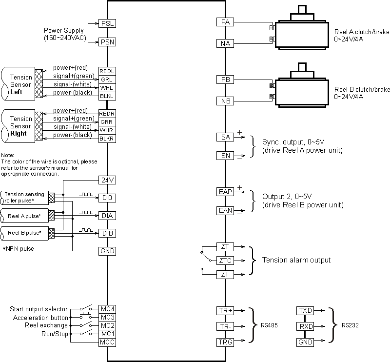
Connect the tension sensor according to the wiring diagram, pay more attention to the wiring of tension sensor if two tension sensors are connected otherwise the measurement value will be incorrect.
-
When one tension sensor is used, make sure to short-circuit the unused tension signal terminals.

2.3.3. Terminals description
Terminal block 1:
Table 2-1. Terminal block 1
| SN | Terminal | I/O | Specification | Comments |
|---|---|---|---|---|
| 1 | PSL, PSN | IN | 85-264V AC, 50/60 Hz | Controller Power supply |
| 2 | ZT, ZTC | OUT | Relay, 3A/250VAC, NO | Tension alarm output |
| 3 | PA, NA | OUT | 24V/4A or 90V/10A | drive Reel A magnetic powder clutch/brake |
| 4 | PB, NB | OUT | 24V/4A or 90V/10A | drive Reel B magnetic powder clutch/brake |
| 5 | MCC | IN | External switch/button input common terminal | |
| 6 | MC1 | IN | Run/Stop | |
| 7 | MC2 | IN | Reel exchange | |
| 8 | MC3 | IN | Acceleration button | |
| 9 | MC4 | IN | Start output selection | |
| 10 | +24V, GND | OUT | 24V DC | Power supply for proximity switch/Encoder |
| 11 | DI0 | IN | Max frequency 15kHz | Tension sensing roller proximity switch pulse input |
Terminal block 2:
Table 2-2. Terminal block 2
| SN | Terminal | I/O | Specification | Comments |
|---|---|---|---|---|
| 1 | DIA | IN | Max frequency 15kHz | Reel A proximity switch pulse input |
| 2 | DIB | IN | Reel B proximity switch pulse input | |
| 3 | GRL | IN | 0-200mV or 0-20mV | Left tension sensor signal+ |
| 4 | WHL | IN | Left tension sensor signal- | |
| 5 | REDL | OUT | 5V or 10V | Left tension sensor power supply+ |
| 6 | BLKL | OUT | Left tension sensor power supply- | |
| 7 | GRR | IN | 0-200mV or 0-20mV | Right tension sensor signal+ |
| 8 | WHR | IN | Right tension sensor signal- | |
| 9 | REDR | OUT | 5V or 10V | Right tension sensor power supply+ |
| 10 | BLKR | OUT | Right tension sensor power supply- | |
| 11 | SA, SN | OUT | 0-20mA or 0-5V | Sync. output, 0-5V(drive Reel A power unit) |
| 12 | EAP, EAN | OUT | 0-20mA or 0-5V | Output 2, 0-5V(drive Reel B power unit) |
| 13 | TR+,TR-,TRG | OUT | RS232/RS485 communication interface | |
| 14 | +5V,0V | OUT | Auxiliary power supply |