Chapter 4. Automatic tension control
- Table of Contents
- 4.1. Tension measurement
- 4.2. Operation
- 4.3. Taper tension control
Please debug by stepping through the following steps:
-
Assure that the mounting and connection of the tension controller is completed and correct, and switch on the power.
-
Assure that the mounting and connection of the tension sensor is correct, check the output signal of the tension sensor.
-
Set the tension measurement related parameters to proper value.
-
Make zero and span calibration and check whether the display of the measured tension is correct, if not, go to step [2].
-
Test the tension measurement and driving system in manual operation mode.
-
Switch to automatic mode, set proper value for proportional band and integral time to get the stable control of the web tension.
4.1. Tension measurement
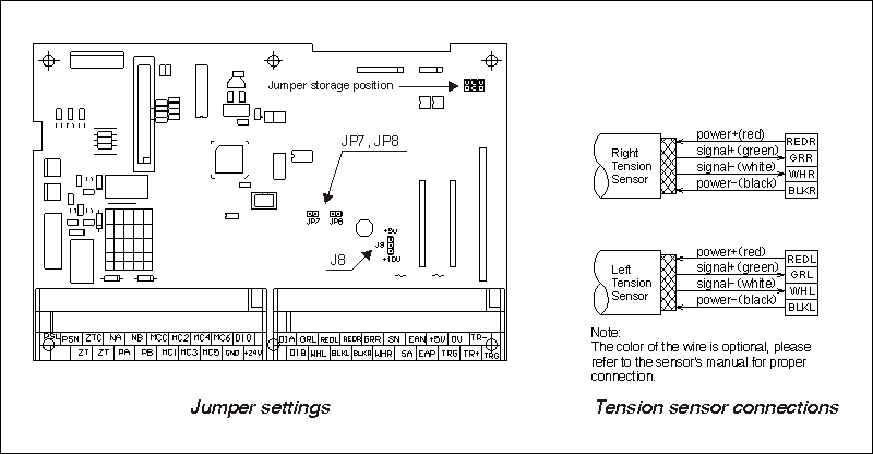
4.1.1. Tension sensor connections
The TC818 can work with various tension sensors. For specific tension sensor, the jumpers JP7, JP8 and J8 must be in the proper position for correct measurement.
-
Using micro-displacment based tension sensor, e.g. the LX series tension sensor(compatible with the Mitsubishi tension sensor). The signal range is 200mV, powered by 5V DC.
Please short-circuit jumpers JP7, JP8, jump J8 to +5V.
-
Using strain gauge based tension sensor, e.g. the SUP, CTS and HTS series tension sensors. The signal range is 20mV, powered by 10V DC.
Please open jumpers JP7, JP8, jump J8 to +10V.
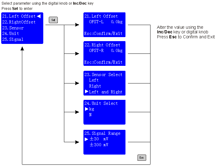
4.1.2. Setting of measurement related parameters
In order to get the precise measurement of the web tension, the measurement related parameters must be set properly:
- Sensor[23]
-
The controller can be used with one or two tension sensors, please make the selection according to the number of the mounted sensors.
- Unit[24]
-
The tension can be displayed in Newtons or Kilograms. Select an unit system, all items which use units will be changed accordingly.
- Signal[25]
-
The controller can be used with two input signal range: ¡À20mV or ¡À200mV, select the proper range according to the sensor.
For LX series tension sensor, select ¡À300mV.
For SUP, CTS and HTS series tension sensor, select ¡À30mV.
- Left Offset[21]/RightOffset[22]
-
The measured tension will drift sometimes, if the drift error is small, the measured tension can be corrected by adding an offset value. But if the drift error is big, the re-calibration of the controller is necessary.
Note that the left and right offset will be reset to 0 after calibration.
- In Filter[44]
-
The controller has a built-in digital filter algorithm, it can cancel the interference and jump of the input signal and make the display of the tension stable.
The greater filter coefficient, the more stable of display of tension but slow response, generally set to 2.00.
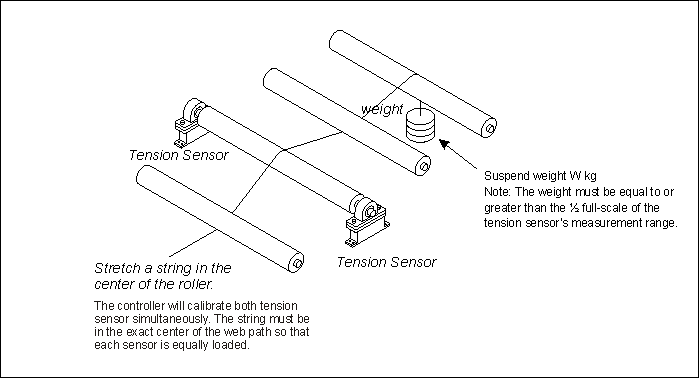
4.1.3. Calibrate tension
In order to perform the closed-loop control to the tension system, the tension controller must be calibrated after installation, and only the proper calibrated controller can get the desirous measurement precision. The controller uses two-points linear calibration method, the process is very easy.
4.1.3.1. Calibration notes
-
Before calibrating, ensure the connection of the sensor is correct and jumpers JP7, JP8, J8 have been set corresponding to the tension sensor.
-
For LX series tension sensor, please short-circuit jumpers JP7 and JP8, jump J8 to +5v and set Signal[25] to ¡À300 mV.
-
For SUP/CTS/HTS series tension sensor, please open jumpers JP7 and JP8, jump J8 to +10v and set Signal[25] to ¡À30 mV.
-
The output signal of the tension sensor can be tested using the multimeter, before testing, please switch the multimeter to the 200mV position.
The output signal should be about 0mV when there is no load applied to the tension sensor.
When applied some force to the tension sensor, the readout on the multimeter will be changed: The bigger force, the stronger signal, but it won't exceed the max output range of the tension sensor, the output signal of LX series tension sensor won't exceed 200mV, for SUP/CTS/HTS series tension sensor, the upper limit is 20mV, if the measured signal exceeds the upper limit, the tension sensor may be damaged, please replace new sensor and reinstall, re-calibrate.
4.1.3.2. Zero calibration
Purpose: To compensate for the sensing roller weight and for any of the other analog zero offset voltages.
Note: The zero calibration must be performed with the weight of the tension sense roller and without material.

4.1.3.3. Span calibration
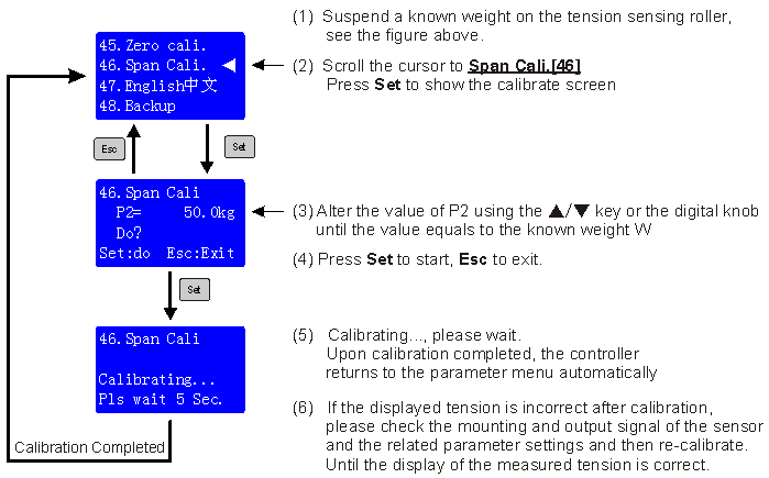
After calibrating, return to the control screen and verify that the display shows zero when no tension is being measured and that the display shows the correct tension value when the weight is applied.